Align every aperture to the mounting datum
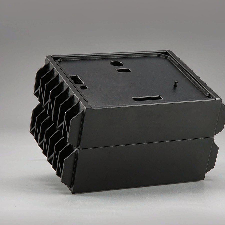
Housings for communication and electronic equipment
Communication & Electronic Enclosures
Machined enclosures where apertures, connector cut-outs and sealing faces must close correctly on the assembled product.
15 years
manufacturing experience
85+
machining & inspection systems
3/4/5-axis
milling, turning & turn-mill
Worldwide
B2B engineering support
Why enclosures are different
Apertures, gasket lands and finish on one datum.
Keep gasket lands flat enough to seal
Hold thin walls straight through anodising
Protect visible faces from clamp marks
Verify fit against the real board or chassis
01
Housing geometry in practice
A machined enclosure concentrates a display window, connector cut-outs, mounting bosses and a gasket land into a thin-walled body. Each feature is measured from the same datum, so any datum shift shows up as a misaligned connector.
Deep pockets and tall walls deflect under clamping. Support strategy, step-down depth and finishing allowance are planned together to keep the walls straight.
- Front panels and bezels
- Vented heat-dissipation housings
- Sealed enclosures with gasket lands
- Backplates and interface panels
02
Surface, coating and fit
Anodising exposes tool marks and clamp witness, so machined surfaces are planned as visible surfaces. Clamping points move away from cosmetic faces and deburring is specified rather than assumed.
Coating thickness changes the fit of press-in parts and the flushness of a bezel, which is why the finish specification is agreed before production.
03
Assembly-level inspection
Inspection checks aperture positions to the mounting datum, gasket-land flatness, boss heights and overall squareness.
Where mating boards or seals are supplied, a trial assembly is the clearest evidence that the enclosure will close and seal.
Prototype to production
A practical B2B manufacturing path
Every stage stays connected to the approved drawing, revision and purchasing requirement.
-
01
Interface review
Confirm board outline, connector positions and sealing design.
-
02
Fixture planning
Place clamps away from cosmetic faces and gasket lands.
-
03
Finish trial
Validate surface preparation and anodising on a sample.
-
04
Batch control
Freeze programs, fixture references and finish specification.
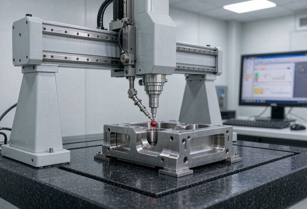
Inspection scope defined before production
Quality evidence for supplier approval
Inspection follows the assembly relationships in the drawing and the finish specification agreed at quotation.
- Aperture position to the mounting datum
- Gasket-land flatness and surface condition
- Boss height and wall thickness
- Anodising colour and coating thickness
- Trial assembly with supplied parts
Engineering and procurement FAQ
Answers before you request a quote
Can you machine a housing from a purchased extrusion?
Yes, and it often reduces material cost on long constant-section parts. Wall variation in the extrusion is accounted for in the setup.
How is a gasket land verified?
Flatness and surface condition are measured against the drawing, then confirmed with a trial assembly where a seal is supplied.
Do you supply inserts and press-fit parts?
Inserts can be installed as part of the assembly scope; the retention method is agreed with the drawing.
What about EMI or shielding requirements?
Conductive finishes and contact surfaces are quoted per project once the shielding requirement is stated.
Start with complete project data
Send your drawings for engineering review.
Include STEP files, 2D drawings, material, quantities, tolerances, finish, inspection and delivery requirements.