Hold motor-mount spacing so props track true
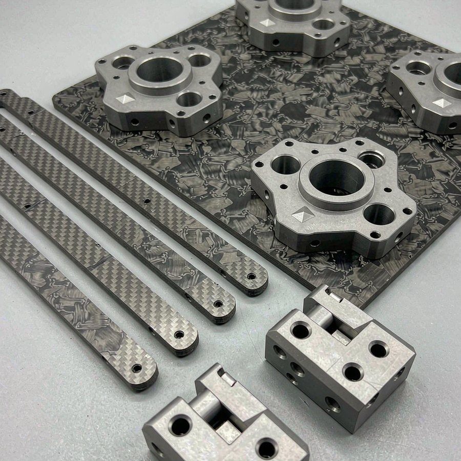
Heavy-lift and commercial UAV platforms
UAV & Drone Parts
Airframe plates, motor mounts and hinge blocks machined for stiffness at minimum weight, with interfaces that repeat across a fleet.
15 years
manufacturing experience
85+
machining & inspection systems
3/4/5-axis
milling, turning & turn-mill
Worldwide
B2B engineering support
Why UAV parts are different
Weight out, stiffness in, interfaces repeatable.
Keep arm interfaces identical across a fleet
Remove weight without softening the load path
Protect fastener holes from wear in repeated assembly
Document each build against a revision
01
Airframe and mount geometry
Drone structures are usually plates and brackets with a demanding weight target and a tight interface requirement. Motor mounts decide thrust line alignment; arm clamps decide whether the frame stays square after a hard landing.
Machining those interfaces in one setup keeps hole patterns and faces consistent, which is what allows a spare part to fit an existing airframe.
- Centre plates and arm plates
- Motor mounts and prop adapters
- Landing gear and gimbal brackets
- Battery trays and equipment mounts
02
Material and finish choices
Carbon plate is normally cut and drilled; aluminium 6061 or 7075 is machined where the part needs threads, bearing seats or a structural pocket. Mixed assemblies combine both.
Anodising protects aluminium interfaces from wear during repeated assembly, and it is agreed alongside the hole tolerance because coating thickness changes fit.
03
Inspection for fleet consistency
The critical checks are hole spacing across the mount pattern, face flatness at the arm interface and overall plate flatness after pocketing.
Because parts are interchangeable across a fleet, batch-to-batch consistency matters as much as single-part accuracy.
Prototype to production
A practical B2B manufacturing path
Every stage stays connected to the approved drawing, revision and purchasing requirement.
-
01
Load path review
Identify the structure carrying thrust and landing loads.
-
02
Pocket strategy
Remove mass while keeping ribs and fillets effective.
-
03
Fit trial
Assemble the airframe and confirm arm alignment.
-
04
Batch repeat
Keep programs fixed so spares match earlier builds.
Inspection scope defined before production
Quality evidence for supplier approval
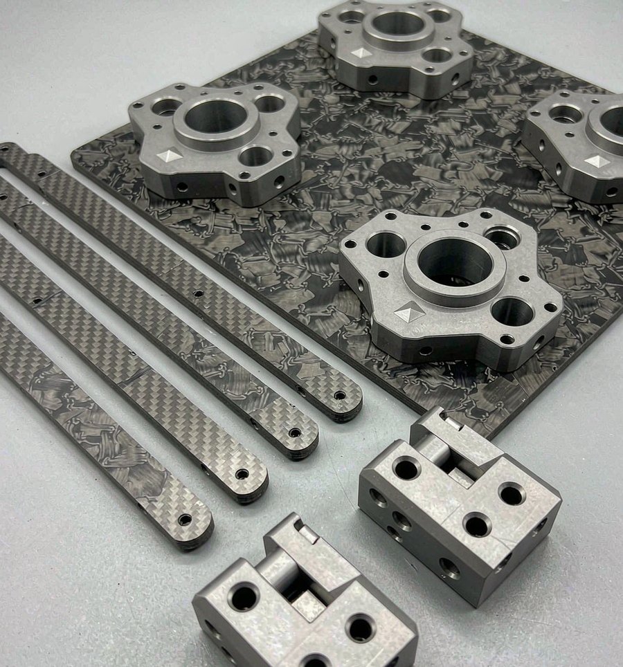
Inspection targets the interfaces that determine thrust alignment and frame squareness.
- Motor-mount hole spacing and position
- Arm interface flatness
- Plate flatness after pocketing
- Thread and insert condition
- First-article and fleet consistency
Engineering and procurement FAQ
Answers before you request a quote
Can you machine carbon fibre plate?
Carbon plate is cut and drilled with tooling suited to abrasive material; aluminium components are machined separately and assembled.
How is weight reduction approached?
Through pocket depth, rib spacing and fillet choice agreed against the load path rather than by removing material indiscriminately.
Do spare parts match earlier airframes?
Yes, provided the drawing revision is the same. Approved programs are retained so that later batches repeat the interface geometry.
Which finishes are typical for UAV brackets?
Anodising for aluminium wear surfaces and bead blasting or painting where appearance or corrosion resistance is the driver.
Start with complete project data
Send your drawings for engineering review.
Include STEP files, 2D drawings, material, quantities, tolerances, finish, inspection and delivery requirements.