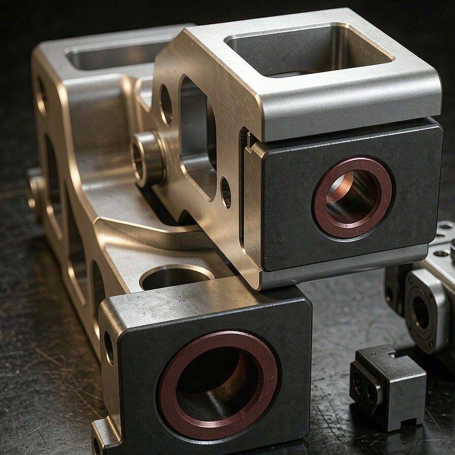
Hold bearing bores coaxial across long frame spans
Humanoid and industrial robotics
Robot Parts Machining
Structural frames, joint housings and lightweight links machined so that bore alignment and mass distribution both survive assembly.
15 years
manufacturing experience
85+
machining & inspection systems
3/4/5-axis
milling, turning & turn-mill
Worldwide
B2B engineering support
Why robot parts are different
Stiffness, mass and bore alignment in one part.
Remove mass through pockets without losing stiffness
Keep mounting faces square to the joint axis
Repeat the same geometry across successive build revisions
01
Frame and joint geometry
A robot link is usually a long thin structure interrupted by bearing seats, motor mounts and cable routes. The bearing seats set the motion; the pockets set the mass; both sit on the same part and therefore on the same datum problem.
Machining both sides in one orientation, or re-establishing the datum precisely, is what keeps the joint axis true once the actuator is installed.
- Humanoid limb links and torso frames
- Joint housings with bearing bores
- Motor and gearbox mounting plates
- End effectors and gripper bodies
02
Material and mass strategy
Aluminium 6061 and 7075 cover most frames; magnesium and titanium appear where mass dominates. Pocket depth, rib thickness and fillet radius are agreed early because they drive both stiffness and machining time.
Thin walls move under clamping and cutting force. Support strategy and finishing allowance are planned before the first cut, not corrected afterwards.
03
Inspection for assembly
Inspection concentrates on bore position relative to the mounting datum, coaxiality across separated bores, and face squareness. Those three relationships predict whether the joint will bind.
Where a customer supplies the actuator, a trial assembly on the machined frame catches interference that drawings alone will not show.
Prototype to production
A practical B2B manufacturing path
Every stage stays connected to the approved drawing, revision and purchasing requirement.
-
01
Structure review
Check frame stiffness, pocket depth and bore accessibility.
-
02
Datum strategy
Establish the joint axis and hold it through both setups.
-
03
Sample build
Test fit with actuator and bearing components.
-
04
Revision control
Track drawing revisions across successive build iterations.
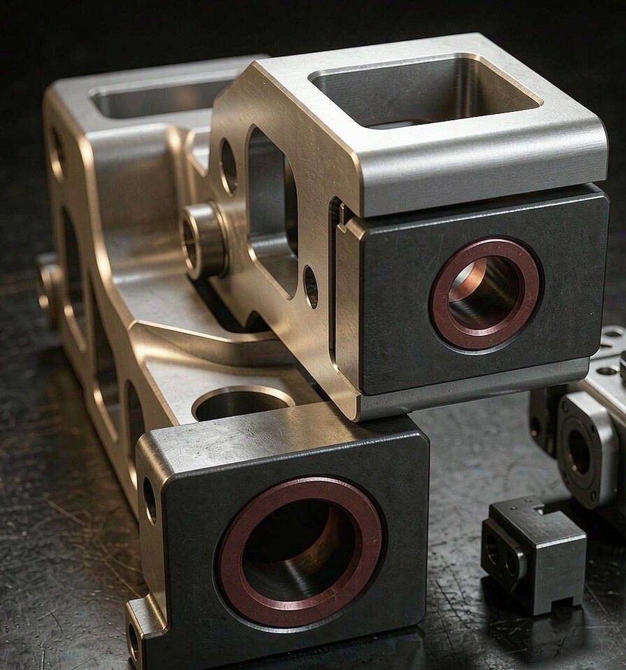
Inspection scope defined before production
Quality evidence for supplier approval
Inspection is built from the motion relationships that decide whether the joint assembles and runs freely.
- Bore position to the mounting datum
- Coaxiality across separated bores
- Face squareness to the joint axis
- Wall thickness after pocketing
- First-article and repeat-batch consistency
Engineering and procurement FAQ
Answers before you request a quote
Which aluminium grade suits a robot frame?
6061 is the usual starting point; 7075 is chosen where strength per kilogram matters more than weldability or cost.
How do you hold tolerance on a long thin link?
Support the part across its length, take light finishing passes and keep the datum consistent between setups.
Can you support frequent design iterations?
Yes. Revision control is part of the process, so each build is traceable to a specific drawing release.
Do you machine magnesium alloys?
Magnesium is quoted per project; it needs specific handling and finishing provisions that are agreed beforehand.
Start with complete project data
Send your drawings for engineering review.
Include STEP files, 2D drawings, material, quantities, tolerances, finish, inspection and delivery requirements.